Why Cantex ?

Why Cantex ?

Their material is UV-stabilized for weathering strength in the changing climate of Northern Ohio. It also machines and drills consistently. The dielectric constant is the same from piece to piece, and the Cantex compound resists chalking. I've filled a dumpster with look-alike parts that failed to survive the coiling process at some point.

See http://www.cantexinc.com for specifications.

The information presented here is accurate and true to the best of the author's knowledge. All recommendations and statements are made without guarantee on the part of the author. The author disclaims any liability in connection with the use of this information.

Monday, September 30, 2019

A first attempt at winding with 3/32" wire


Before winding, the tube is cleaned and blue painter's tape is applied at one inch intervals around the entire section. A thin coating of DAP Alex Plus acrylic caulk is applied to the spaces between the tape lines and allowed to dry for 24 hours. The caulk strips will hold the wire in place during and after winding.


Here the tape is removed in preparation for winding. The wire transport used in prior projects has been rebuilt using wood instead of plastic parts for weight reduction. The sheave on the headstock has also been replaced with a wooden disk. 

This is the test setup for the new drive. The bulky old pulley fixture had no speed control and is replaced by the Harbor Freight variable speed polisher , HF item number 60626. The polishing pad is replaced by a small pulley from a clothes washing machine sized to accommodate the 1/4" drive belt shown here.

The polisher has a speed range pot embedded in the handle
which can be set to any speed the operator likes. 


The drive is attached to carton for easy alignment with the drive sheave. It's own weight is enough to provide medium tension on the drive belt.


A door hinge attaches the drive to the carton. Now the optimum location for the drive is set directly
underneath the wood sheave.


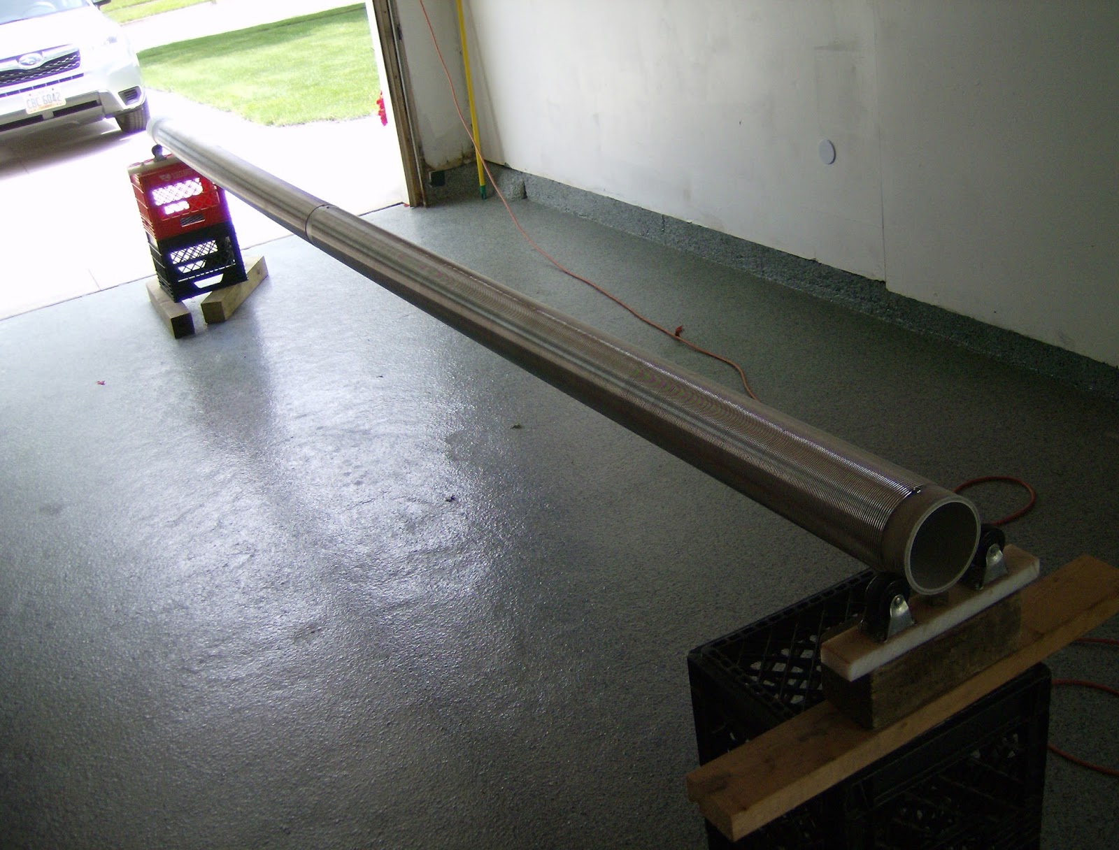
The wind at the half way point. The 3/32" wire bites into the acrylic strips for consistent alignment.


The finished piece is 9 feet tall, sports 500 turns of wire, and is even free standing !

Here's a closeup of the finished coil. 


A homemade wire guide is shown here. The clear plastic tubing has a 1/8" id  and comes from the stem of a bottle of spray cleaner. The yellow base is a shim used to align ceramic parts. 

The two are held together with Harbor Freight Super Glue.

 As the coil form rotates, the wire is drawn through the tubing and the space between the turns, or pitch, is maintained by the edge of the shim rubbing against the previous turn, held in place by the operator's hands.

Sunday, September 2, 2018

The latest version is up and running...

The .045" stainless steel wire version is finished and set up. The new base section keeps the XLY's flowers out of harm's way.

Have an opinion or observation ? Please let me know. Thanks.

showman_44221@yahoo.com


Saturday, September 1, 2018

At the Half Way Point


The first half of the project is completed. It took about 5 hours to wind at a surface travel speed of 138 inches per minute. DC resistance is measured at 295 Ohms. The wire is 309 stainless, .045" diameter.

The adhesive used on the original job with this Cantex section is still pliable, and will hold the wire in position. The best tool I've found for pruning the coil is the human fingernail. If you have a better idea, please let me know.

Setup Complete


The new setup includes idle support wheels that float the tube in an X/Y pattern as opposed to the old wheels which simply rotated in one direction. The 6" tube has a tendency to travel in one direction, the the newer idlers minimize the motion.

The brick shown above keeps the main rotation motor stand from moving as coiling progresses. Over three of four hours, the drive will move on it's own enough to require operator intervention if not held in place securely.

The new wire guide is the cartridge from a ballpoint pen. It's ID is .046 - .048 " and it's wall is .024 -.025". It seems to be made of tough material, and it's perfect for closely spaced wire winding. The goal is to stuff 15 turns of wire into 1 inch of coil form. This translates into approximately 1388 feet of wire per half of the dipole antenna using .045" wire.


Tuesday, August 28, 2018

Beginning a New 6 Inch Project, August 2018

The wire from the old vertical dipole antenna is  stripped off, and the 10' Cantex tube section is ready for a new life.

The support brackets have extra height due to the addition of another carton on each end. The tube is now at eye level for the operator, affording better control and inspection of the winding process.

To accommodate the operator, an extension has been added to the plain end of the tube.

We'll be winding close to the end of the tube, and the idler wheel set has always been in the way.

Adding an 18" extension solves this problem.

The photo on the left shows the 18" piece with an internal alignment mandrel placed on a viewing stand. The arbor is 48 inches long, and fits inside both the extension and the tube. It's made of 2 x 6 scrap lumber, cut into three pieces to form a cross. The wooden  assembly is held together by pressure from the extension, and has a sliding fit inside the main tube. For rigidity, the insert should be set at least 2 feet into the main tube. As the main tube rotates, the extension rolls at the same speed and there is no chatter or vibration. Assembly and disassembly are both quick and easy. And the price is right.


Here the extension is attached. The screw that secures the end of the coil wire is close in length to the wall of the tube: about .238".


Friday, June 8, 2018

Connected and Ready to Go !


The finished part is set up in an out-of-the-way corner so as not to be obtrusive. This is the quintessential all-band ham radio antenna for restricted lot use. The simple neighbors' unwelcome curiosity is kept to a minimum by the low profile, and the XYL can still populate the area with her nefarious green things. 


The tooling is removed and a completed dipole antenna is ready for action. Weight is about 70 pounds, so exercise some caution.

With any garage project using junk parts, unwanted variations in alignment and fit up make their way to the finished product. The Lash shims, or "Wedges", shown here are indispensable for correcting and fixing minor things that need adjustment. A bag of 50 pieces is available at The Home Depot for around $9.00. A very good deal considering...

www.LASHspacer.com

Tuesday, June 5, 2018

Half of the dipole is complete: 53.5" of wind with .062" (1/16") wire. Approximately 742 feet. Measured DC resistance is 58 ohms.

Monday, June 4, 2018

The head stock and drive motor are lined up and ready for winding. That 14" section from the first slide adds the extra length for winding at the tube base. Now we need the rubber hammer for end-to-end alignment.
Both ends of the 10' tube section are marked every 60०. These indicate the centers for Dynaflex 230 adhesive strips (6) which will secure the wire windings on the tube. It's available at The Home Depot. Although sold as a window sealant, the all-weather characteristics of the '230 make it ideal for this application. See the manufacturer's web site for usages and safety data; http://www.dap.com/dap-products-ph/dynaflex-230-premium-indooroutdoor-sealant/
Use 3/4 to 1 inch spacing for the sealant strip width. Blue painter's tape is used to set the space. Use your fingers cover the gap with a very thin coating of sealant. Disposable latex gloves come in handy for this job. 
Allow the goop to set up for at least 4 hours before removing the tape. These strips will secure the wire in position by forming small landing pads that stay flexible for a long time. And it's inexpensive.

The new 6" flange is mounted to the original sheave. The 14" tube section on the right will serve as the connector between the head stock and the coil form. It's cut from a junk piece of schedule 80
tube. Normally it would be glued to the flange socket, but not in the case of 6" tubing. 
Both the socket seat and the end insert are coated with automatic transmission fluid. The ATF compound has tremendous film strength, and keeps the insert from seizing in the socket seat for quick disassembly.  Final alignment of the fixture involves using a rubber hammer, so glue is ruled out.

The blue painter's tape shown here defines the channel for the Dab adhesive. Chalk lines are helpful for siting the tape position but are not necessary. The glue is applied by hand for a thin coating along the entire length of the tube. Wait at least three hours before removing the tape. The wire will find a permanent seat on the sealant immediately as winding proceeds. 
The operator's mobile station is in position. The on/off control line is behind the fixture so as not to be run over by the transport wheels. There is no brake on the motor, so rotation will continue for 2 to
3 seconds after the power is turned off. The control switch can be seen just to the left of the wire spool.

Wednesday, May 16, 2018

The Ugly Balun is attached to the dipole. It's wound with RG6/U.


Wednesday, June 28, 2017

The 20 footer goes together


Monday, June 26, 2017

The new schedule 40, 4 inch, 20 foot section arrives from Mars Electric.

Getting the piece off the truck and carrying it into my garage, I learn one thing immediately;
it's too big for me to handle.

The first thing to do is to trim it down to 15 feet.


The bell end of the tube is resting on the idler roll in the background. The cut end is in the foreground
and will be fitted with a Cantex 4" coupler, P/N 6141632.

The coupler has perfectly trimmed edges and with the face of the headstock fitting the two edges  form a channel for the headstock support wheels. Now there is no travel of the tube in the fixture.

Next, the A52EA42 will get all taped up in preparation for applying the Dap Dynaflex 230 (clear)
caulking compound. The blue painter's tape is used to make 3/4" channels every 60 degrees of rotation, or 6 channels, on the entire length of the tube. The Dap material goes on white and is spread on the channels with the fingers to form a thin coating.


  When it drys to a clear finish, it's time to peel off the tape.


Four holes are drilled next; two for each half of the dipole. A one inch space is left in the center
for mounting the coaxial cable retaining clamp.


Above, one half of the winding job is complete. The aluminum .062" (1/16") wire goes on smoothly and the Dynaflex 230 holds it in place perfectly. Coiling time for the 82" section is about 3 hours.
The on/off switch is mounted just to the left of the wire spool. There are always frequent starts and stops, and this is a convenient place for the operator. Also notice the glasses on the seat behind the spool. These are 3.5 dioptre in strength, and are necessary to pinpoint the exact location of the wire
and the guide tool.

To end the job, we'll start the second half from the opposite end of the tube, close to the headstock.


Finally, we're done winding, and only the coaxial cable connection remain.


Standing next to the garage, the finished product. The vertical dipole has two coils each 82 inches
long. 779 feet of wire cover each half.


Note !

The XYL's plants must be protected at all costs !


Wednesday, November 16, 2016

Another approach for wire stability

Today we'll tackle the problem of coil stability in a new way.

Here is a new 10' section of schedule 40 4" Cantex, ready for cleaning. Scotch-Brite and windshield washer fluid are used to remove small surface nicks and dirt.


The two black plastic brackets holding the tube are called base spacers in Cantex-speak, part number
5355969, and are not very expensive. They come in very handy if you do any work with 4" material.

After cleaning, a protractor is attached to the bell end of the tube.

We'll make hash marks every 60 degrees, for a total of six on the circumference.

The protractor is fastened to the other end of the tube, and six more hash marks are drawn. Now we
have two end points for the next step, snapping a chalk line.
Next, we uses blue painter's tape to make a 1/2 inch channel.
Half of the tape is shown here. We remove the chalk line before putting on the second tape border.
With both tape lines in place, we're ready to apply the wire stabilizer. This is a very thin coating of DAP
Dynaflex 230 caulking compound, purchased from the Home Depot. Please read the instructions on the container. This stuff sticks to PVC and is useful over a wide temperature range. You may want to make a practice run first. Try putting down a bead about 1/10 of an inch in diameter.Then use a latex glove or wrap your index finger in plastic wrap and smooth out the caulk manually. The goal is to make a small adhesive pad for the coiled wire. Give the Dynaflex 5 minutes to set up before removing the tape.


The thin caulk line presents a low profile on the tube. Next, we wind the coil.


Wednesday, November 4, 2015

Another approach to coil stability.

The brake on the wire spool hub is set to hand tight plus three quarters of a complete turn. This yields a very high wire tension on the coil feed wire. The results are a uniform wind and no shift of wire on the form.


It doesn't get better than this. The whole 10 foot tube shows this consistency !
Here is another lathe shot:


This is a picture of the wire spool stand and the tube, at the half way point in construction.


And here is the finished antenna;

I fired this coil up on the low end of forty meters and was pleasantly surprised. I found three resonance points on the tuning capacitor on my MFJ antenna turner, and each time I changed frequency slightly on my transceiver, I had to reset the MFJ unit.
The next step will be a twenty footer !!! Must wait for the return of warmer weather.
A quick note to the coil builder. Stay with the Cantex conduit. I had occasion to try to use brand x PVC electrical conduit for a test trial and ran into serious problems;
1. Check for rigidity. The "x" 10 foot section took a bend on the way home in the back of my car. Not good.
2. Try drilling holes for tap positions. I drilled six holes; two were difficult and four went through the material like butter. Not good.
3. Here's the show stopper. The bell end was not sized correctly. It seized on my sheave mandrel and was an absolute nightmare to remove. Really not good.
In fairness to the conduit industry, I must point out that their product(s) are not designed for my applications.